The OSI (Open Systems Interconnection) model is like a framework used to separate the specific roles, responsibilities, and technologies of computer networks into individual layers to avoid becoming overwhelming.
Outside of the classroom, the layers are primarily used to discuss one particular aspect of particular communication or to assist in troubleshooting one particular slice of it. It’s not a chart you will ever likely refer to, but more a mental picture you will develop as you build up experience and deeper understanding of how networks work (or don’t).
For even the most simple operations such as sending an email can get incredibly complex once you start discussing it in technical details.
An example of how you’d break down an email into its 7 OSI layers:
- The data is sent as electrical signals, light pulses, or radio waves using ethernet cables, wifi signals and fibre optic cables.
- Networking hardware such as Switches and Access Points ‘switch’ (send) the data frames across the local network to the internet gateway (router))
- Routers prepare this data to be sent between networks by assigning the data packet a source and the destination IP address of the mail server. It will then ensure its sent via the correct path across the internet using a network route.
- Protocols such as TCP are used to send data reliably and error free
- The router uses NAT to open up session to the email server so there is connectivity between the two devices so communication can begin
- The email client and mail-server use SSL/TLS to securely encrypt and decrypt the message in an agreed upon common format so the message can be transmitted securely
- The email client once established, will use the SMTP protocol and use the commands such as HELO, MAIL FROM, RCPT TO, DATA to configure the mail server with the details it needs to send the email.
The Seven Layers of the OSI Model
Layer 1: Physical Layer
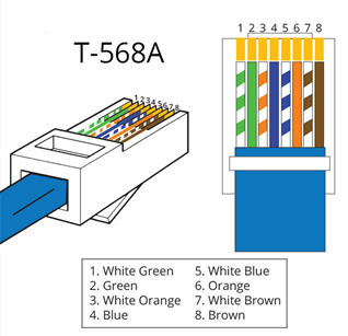
The physical layer (Layer 1) is focuses on how raw bits (0s and 1s) are transmitted over a particular medium, such as a ethernet cable, fiber optic cable, or radio waves.
It is considered the lowest of layers.
Responsibilities
- Physical connections: Connector types and sizes
- Electrical Signals (Voltages, Timing, Frequencies)
Protocols and Technologies
- Ethernet (Physical aspects of Ethernet frames)
- IEEE 802.3 (Ethernet standards)
- DSL (Digital Subscriber Line)
Layer 2: Data Link Layer
Layer 2 is focused on sending frames between devices error free across a single network.
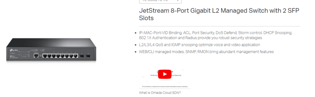
An important point is Layer 2 only uses MAC Address (Physical Address) to identify clients and not IP Address. This is why a network switch is often advertised as a L2 device.
Protocols and Technologies
- Ethernet (MAC addresses and frame structure)
- Wi-Fi (IEEE 802.11) (Wireless LAN technology)
- PPP (Point-to-Point Protocol) (Direct connections between two nodes)
- ARP (Address Resolution Protocol) (Mapping IP addresses to MAC addresses)
- VLAN (Virtual LAN) (Network segmentation)
Layer 3: Network Layer
Layer 3 differs from layer 2 in that it primarily focuses on routing data packets between networks.
The easiest way to distinguish this is Layer 3 uses IP addresses to route packets, while a layer 2 device such as a switch uses MAC addresses.
The network defines what is a network is, using an IP address of the network and subnet mask to define how large the network is.
Unlike Layer 2 Switches which may have up to 48 network ports workstations directly plug into, routers often only small number of interfaces. This is as typically they are only plugged into a WAN or two, and a network switch for local traffic.
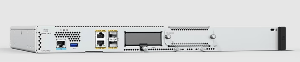
It is important to note ‘routing’ Layer 3 Traffic between networks is slow and requires significant computing power while ‘switching’ on a local network is easy. An example of this you can buy a $10 gigabit switch which will easily handle multiple gigabit’s of traffic being passed through it and only use a few watts of power, on other hand a router which can route at gigabit speed may cost hundreds of dollars and need active cooling because it requires so much power.
One of the important tasks of a router is to send the data in the correct path across the internet.
This is done using a routing table containing a map of the other networks routers on the internet. These tables are generated by ‘learning’ the routes of other connected routers using protocols such as BGP and OSPF. In almost all cases the router will not know the entire network or internet, but enough to send the data to another router closer to the destination.
Protocols and Technologies:
- IP (Internet Protocol): IPv4, IPv6
- ICMP (Internet Control Message Protocol): Error messages and diagnostics
- IGMP (Internet Group Management Protocol)
- OSPF (Open Shortest Path First) (Routing protocol for large networks)
- BGP (Border Gateway Protocol) (Routing protocol)
Layer 4: Transport Layer
The main focus of the Transport Layer (Layer 4) is the reliable data transfer between end systems.
This includes optional features of error recovery and flow control.
Protocols and Technologies:
Two main protocols are used, TCP & UDP. Both have there advantages and disadvantages with the protocol choice set by the application.
- TCP (Transmission Control Protocol): Reliable, connection-oriented communication, TCP three-way handshake. Used when reliable data transfer is needed such as to send an email or transfer a file. If the sender does not confirm they received the packet or if it contains an error, it will be sent again.
- UDP (User Datagram Protocol): Connectionless, fast and low latency, minimal overheads, less reliable, no guarantee the receiver will actually receive the data or in what order. No flow control or error correction.
Used when maximum performance and the lowest latency and where reliability or data loss is not critical, such as VoIP, video call and position data for multiplayer games
The below meme sums up what both protocols are!
- TCP will carefully initiate a conversation and hand over the parcel when you are ready, confirming you received it in one piece
- UDP doesn’t have time for that! It will be sent if you are ready or not and doesn’t care if it arrives damaged or gets lost

Layer 5: Session Layer
Layer 5 (Session) is primarily responsible for Establishes, manages, and terminates connections between applications on different devices.
Responsibilities: Manages sessions and dialogues between applications, handling session establishment and teardown.Protocols and Technologies:
- NetBIOS (Network Basic Input/Output System) (Session management and communication in early networks)
- RPC (Remote Procedure Call) (Remote communication between programs)
- PPTP (Point-to-Point Tunneling Protocol) (VPN session establishment)
Layer 6: Presentation Layer
Handles data encryption, decryption, compression, and formatting, ensuring that data is presented in a readable way for the application layer
Layer 7: Application Layer
The top layer where end-users interact with network services. It provides protocols that applications use to communicate over the network, such as HTTP for web browsing, FTP for file transfer, and SMTP for email.
(Layer 8: User Layer)
‘Layer 8’ is not typically included as part of the official OSI model, but it is used to describe factors outside the technical scope of networking that can affect network performance and management.
Examples of this often relate to user error, lack of training and device misconfiguration!

Separation of layers & Troubleshooting
One of the major benefits of the OSI model is each layer for the most part is isolated from the rest, this is where its benefits
For example if the user was connecting to the mail-server and getting a “Authentication Failed: Invalid Password”, you’d instantly think this a layer 7 issue of an outdated password being set in the email client, or a layer 8 problem with the user being forgetful! You wouldn’t think it was a layer 1 issue where you blame a faulty ethernet cable.
Limitations of the OSI Model
It’s important to remember that in the real-world, networks and communications don’t always strictly follow the OSI model.
Examples of this may include:
- Applications such as Encrypted Messengers may encrypt the message in the application layer (layer 7) and not just be reliant on HTTPS/SSL in the presentation layer (layer 6)
- Advanced Hardware Technologies: Devices such as Multi-Layer (L3) Switch’s and network appliances can blur the line on what exactly what each component does. For example a switch ‘may’ route traffic between other internal networks (inter-vlan routing) or a commercial router may just not route traffic, but also scan the contents of the data for malware using DPI (Deep Packet Inspection).
- Protocol Optimisation: Many protocols have begun spanning multiple layers to improve
performance, an example of this is HTTP/2 (a layer 7 protocol) which introducing multiplexing, header compression, and prioritization which is traditionally handles in layer 4 – Transport Layer.
Conclusion
Despite the limitations of the OSI Model, it is still a valuable framework to understand and adopt when troubleshooting complex networking problems